Zigzags represent resistors, and a pair of parallel, unequal lines represents a
battery cell. The longer line is the positive terminal and the shorter line is
the negative terminal. That means the current flows from the longer line around
the circuit to the shorter line. In the diagram above, the current flows
counterclockwise. Often, more than one set of unequal parallel lines are
arranged together; this just signifies a number of battery cells arranged in
series.
Example
In the diagram above,
e=
6 V and R = 12
O.
What is the current in the circuit and what is the power dissipated in the
resistor?
You don’t really need to refer to the diagram in order to solve this problem. As
long as you know that there’s a circuit with a six-volt battery and a
12-ohm resistor, you need only apply Ohm’s
Law and the formula for power.
Since I = V/R, the current is:

The power is:
P = I2R = (0.5A)2(12O) = 3W
Resistors in Series
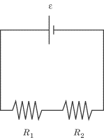
Two resistors are in series when they are arranged one after another on
the circuit, as in the diagram below. The same amount of current flows first
through one resistor and then the other, since the current does not change over
the length of a circuit.
Video Lesson - Resistors in Series
However, each resistor causes a voltage drop, and if there is more than one
resistor in the circuit, the sum of the voltage drops across each resistor in
the circuit is equal to the total voltage drop in the circuit. The total
resistance in a circuit with two or more resistors in series is equal to the sum
of the resistance of all the resistors: a circuit would have the same resistance
if it had three resistors in series, or just one big resistor with the
resistance of the original three resistors put together. In equation form, this
principle is quite simple. In a circuit with two resistors,
R1
and
R2,
in series, the total resistance,
R1
is:
R1 = R1 + R2
Examplee
In the figure above, a battery supplies 30 V to a circuit with a 10
O
resistor and a 20
O
resistor. What is the current in the circuit, and what is the voltage drop
across each resistor?
What is the current in the circuit?
We can determine the current in the circuit by applying Ohm’s Law:
I = V/R. We know what
V is, but we need to calculate the
total resistance in the circuit by adding together the individual resistances of
the two resistors in series:
R1 = R1 + R2 = 10O + 20O = 30O
When we know the total resistance in the circuit, we can determine the current
through the circuit with a simple application of Ohm’s Law:

What is the voltage drop across each resistor?
Determining the voltage drop across an individual resistor in a series of
resistors simply requires a reapplication of Ohm’s Law. We know the current
through the circuit, and we know the resistance of that individual resistor, so
the voltage drop across that resistor is simply the product of the current and
the resistance. The voltage drop across the two resistors is:
V1 = IR1 = (1A)(10O) = 10V
V2 = IR2 = (1A)(10O) = 20V
Note that the voltage drop across the two resistors is
10 V + 20
V = 30 V, which is the total voltage drop
across the circuit.
Resistors in Parallel
Two resistors are in parallel when the circuit splits in two and one
resistor is placed on each of the two branches.
Video Lesson - Resistors in Parallel
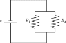
In this circumstance, it is often useful to calculate the equivalent resistance
as if there were only one resistor, rather than deal with each resistor
individually. Calculating the equivalent resistance of two or more resistors in
parallel is a little more complicated than calculating the total resistance of
two or more resistors in series. Given two resistors,
R1
and
R2 ,
in parallel, the equivalent resistance,
R1,
is:

When a circuit splits in two, the current is divided between the two branches,
though the current through each resistor will not necessarily be the same. The
voltage drop must be the same across both resistors, so the current will be
stronger for a weaker resistor, and vice versa.
Example
Two resistors,
R1
= 5
O
and
R2
= 20
O,
are set up in parallel, as in the diagram above. The battery produces a
potential difference of
e
= 12 V. What is the total resistance in the circuit? What is the current running
through
R1
and
R2 ?
What is the power dissipated in the resistors?
What is the total resistance in the circuit?
Answering this question is just a matter of plugging numbers into the formula
for resistors in parallel.

So
R1
= 44
O.
What is the current running through R1 and R2?
We know that the total voltage drop is 12
V, and since the voltage drop is the same across all the branches of a set of
resistors in parallel, we know that the voltage drop across both resistors will
be 12 V. That means we just need to apply
Ohm’s Law twice, once to each resistor:

If we apply Ohm’s Law to the total resistance in the system, we find that
Ii
= (12 V)/(4
O)
= 3 A. As we might expect, the total current through the system is the sum of
the current through each of the two branches. The current is split into two
parts when it branches into the resistors in parallel, but the total current
remains the same throughout the whole circuit. This fact is captured in the
junction rule we will examine when we look at Kirchhoff’s Rules.
What is the power dissipated in the resistors?
Recalling that P = I2R,
we can solve for the power dissipated through each resistor individually, and in
the circuit as a whole. Let
P1
be the power dissipated in
R1,
P2
the power dissipated in
R2,
and
Pi
the power dissipated in
Ri.
P1 = (2.4A)2 (5O) = 28.8W
P2 = (0.6A)2 (20O) = 7.2W
Pt = (3A)2 (4O) = 36W
Note that
P1
+
P2
=
Pi .
Circuits with Resistors in Parallel and in Series
Now that you know how to deal with resistors in parallel and resistors in
series, you have all the tools to approach a circuit that has resistors both in
parallel and in series. Let’s take a look at an example of such a circuit, and
follow two important steps to determine the total resistance of the circuit.
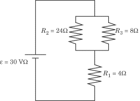
- Determine the equivalent resistance of the resistors in parallel. We’ve
already learned to make such calculations. This one is no different:

So the equivalent resistance is 6
O.
In effect, this means that the two resistors in parallel have the same
resistance as if there were a single 6
O
resistor in their place. We can redraw the diagram to capture this equivalence:
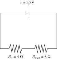
- Treating the equivalent resistance of the resistors in parallel as a single
resistor, calculate the total resistance by adding resistors in series. The
diagram above gives us two resistors in series. Calculating the total resistance
of the circuit couldn’t be easier:
Ri = R1 + R2+3 = 4O + 6O = 10O
Now that you’ve looked at this two-step technique for dealing with circuits in
parallel and in series, you should have no problem answering a range of other
questions.
Example
|
|

|
|
|
Consider again the circuit whose total resistance we have calculated. What is
the current through each resistor? What is the power dissipated in each
resistor? |
What is the current running through each resistor?
We know that resistors in series do not affect the current, so the current
through
R1
is the same as the total current running through the circuit. Knowing the total
resistance of the circuit and the voltage drop through the circuit, we can
calculate the circuit’s total current by means of Ohm’s Law:

Therefore, the current through
R1
is 3 A.
But be careful before you calculate the current through
R2
and
R3:
the voltage drop across these resistors is not the total voltage drop of
30 V. The sum of the voltage drops across
R1
and the two resistors in parallel is 30 V,
so the voltage drop across just the resistors in parallel is less than
30 V.
If we treat the resistors in parallel as a single equivalent resistor of
6
O,
we can calculate the voltage drop across the resistors by means of Ohm’s Law:
V = IR2+3 = (3A)(6&Omega> = 18V
Now, recalling that current is divided unevenly between the branches of a set of
resistors in parallel, we can calculate the current through
R2
and
R3
in the familiar way:

What is the power dissipated across each resistor?
Now that we know the current across each resistor, calculating the power
dissipated is a straightforward application of the formula
P = I2R:

Common Devices in Circuits
In real life (and on Physics) it is possible to hook devices up to a
circuit that will read off the potential difference or current at a certain
point in the circuit. These devices provide Physics with a handy means of
testing your knowledge of circuits.
Voltmeters and Ammeters
A voltmeter, designated:

measures the voltage across a wire. It is connected in parallel with the stretch
of wire whose voltage is being measured, since an equal voltage crosses both
branches of two wires connected in parallel.
Video Lesson - Voltmeters and Ammeters
An ammeter, designated:

is connected in series. It measures the current passing through that point on
the circuit.
Example
|
|
|
|
|
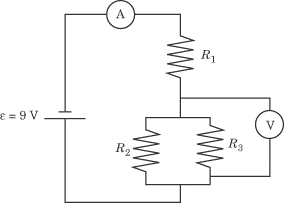
In the diagram above,
e
= 9 V,
R1
= 5
O,
R2
= 5
O,
and
R3
= 20
O.
What are the values measured by the ammeter and the voltmeter? |
What does the ammeter read?
Since the ammeter is not connected in parallel with any other branch in the
circuit, the reading on the ammeter will be the total current in the circuit. We
can use Ohm’s Law to determine the total current in the circuit, but only if we
first determine the total resistance in the circuit.
This circuit consists of resistors in parallel and in series, an arrangement we
have looked at before. Following the same two steps as we did last time, we can
calculate the total resistance in the circuit:
- Determine the equivalent resistance of the resistors in parallel.

We can conclude that
R2+3
= 4
O.
- Treating the equivalent resistance of the resistors in parallel as a single
resistor, calculate the total resistance by adding resistors in series.
Ri = R1 + R2+3 = 5O + 4O = 9O
Given that the total resistance is 9
O
and the total voltage is 9 V, Ohm’s Law
tells us that the total current is:

The ammeter will read 1 A.
What does the voltmeter read?
The voltmeter is connected in parallel with
R2
and
R3,
so it will register the voltage drop across these two resistors. Recall that the
voltage drop across resistors in parallel is the same for each resistor.
We know that the total voltage drop across the circuit is
9 V. Some of this voltage drop will take
place across
R1,
and the rest of the voltage drop will take place across the resistors in
parallel. By calculating the voltage drop across
R1
and subtracting from 9 V, we will have the
voltage drop across the resistors in parallel, which is what the voltmeter
measures.
V = I1R1 = (1A)(5?) = 5V
If the voltage drop across
R1
is 5 V, then the voltage drop across the
resistors in parallel is 9 V –
5 V = 4
V. This is what the voltmeter reads.
Fuses
A fuse burns out if the current in a circuit is too large. This prevents
the equipment connected to the circuit from being damaged by the excess current.
For example, if the ammeter in the previous problem were replaced by a
half-ampere fuse, the fuse would blow and the circuit would be interrupted.
Fuses rarely come up on Physics. If a question involving fuses appears,
it will probably ask you whether or not the fuse in a given circuit will blow
under certain circumstances.
Kirchhoff’s Rules
Gustav Robert Kirchhoff came up with two simple rules that simplify many
complicated circuit problems. The junction rule helps us to calculate the
current through resistors in parallel and other points where a circuit breaks
into several branches, and the loop rule helps us to calculate the
voltage at any point in a circuit. Let’s study Kirchhoff’s Rules in the context
of the circuit represented below:
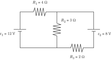
Video Lesson
Before we can apply Kirchhoff’s Rules, we have to draw arrows on the diagram to
denote the direction in which we will follow the current. You can draw these
arrows in any direction you please—they don’t have to denote the actual
direction of the current. As you’ll see, so long as we apply Kirchhoff’s Rules
correctly, it doesn’t matter in what directions the arrows point. Let’s draw in
arrows and label the six vertices of the circuit:
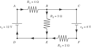
We repeat, these arrows do not point in the actual direction of the current. For
instance, we have drawn the current flowing into the positive terminal and out
of the negative terminal of
e2,
contrary to how we know the current must flow.
The Junction Rule
The junction rule deals with “junctions,” where a circuit splits into more than
one branch, or when several branches reunite to form a single wire. The rule
states:
The current coming into a junction equals the current coming out.
Video Lesson - Junction
This rule comes from the conservation of charge: the charge per unit time going
into the junction must equal the charge per unit time coming out. In other
words, when a circuit separates into more than one branch—as with resistors in
parallel—then the total current is split between the different branches.
The junction rule tells us how to deal with resistors in series and other cases
of circuits branching in two or more directions. If we encounter three resistors
in series, we know that the sum of the current through all three resistors is
equal to the current in the wire before it divides into three parallel branches.
Let’s apply the junction rule to the junction at
B in the diagram we looked at earlier.
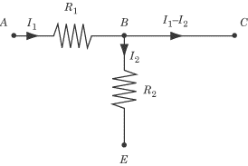
According to the arrows we’ve drawn, the current in the diagram flows from
A into
B across
R1
and flows out of B in two branches:
one across
R2
toward E and the other toward
C. According to the junction rule,
the current flowing into B must
equal the current flowing out of B.
If we label the current going into B
as
l1
and the current going out of B
toward E as
l2,
we can conclude that the current going out of B
toward C is
l1
–
l2.
That way, the current flowing into B
is
l1
and the current flowing out of B is
l2
+ (l1
–
l2)
=
l1.
The Loop Rule
The loop rule addresses the voltage drop of any closed loop in the circuit. It
states:
The sum of the voltage drops around a closed loop is zero.
This is actually a statement of conservation of energy: every increase in
potential energy, such as from a battery, must be balanced by a decrease, such
as across a resistor. In other words, the voltage drop across all the resistors
in a closed loop is equal to the voltage of the batteries in that loop.
In a normal circuit, we know that when the current crosses a resistor,
R, the voltage drops by
IR, and when the current crosses a
battery, V, the voltage rises by
V. When we trace a loop—we can
choose to do so in the clockwise direction or the counterclockwise direction—we
may sometimes find ourselves tracing the loop against the direction of the
arrows we drew. If we cross a resistor against the direction of the arrows, the
voltage rises by IR. Further, if our
loop crosses a battery in the wrong direction—entering in the positive terminal
and coming out the negative terminal—the voltage drops by
V. To summarize:
- Voltage drops by IR when the loop
crosses a resistor in the direction of the current arrows.
- Voltage rises by IR when the loop
crosses a resistor against the direction of the current arrows.
- Voltage rises by V when the loop
crosses a battery from the negative terminal to the positive terminal.
- Voltage drops by V when the loop
crosses a battery from the positive terminal to the negative terminal.
Let’s now put the loop rule to work in sorting out the current that passes
through each of the three resistors in the diagram we looked at earlier. When we
looked at the junction rule, we found that we could express the current from
A to
B—and hence the current from E
to D to
A—as
l1,
the current from B to
E as
l2,
and the current from B to
C—and hence the current from
C to
F to E—as
l1
–
l2.
We have two variables for describing the current, so we need two equations in
order to solve for these variables. By applying the loop rule to two different
loops in the circuit, we should be able to come up with two different equations
that include the variables we’re looking for. Let’s begin by examining the loop
described by ABED.
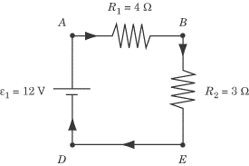
Remember that we’ve labeled the current between
A and B as
l1
and the current between B and
E
l2 .
Because the current flowing from E
to A is the same as that flowing
from A to
B, we know this part of the circuit
also has a current of
l1 .
Tracing the loop clockwise from A,
the current first crosses
R1
and the voltage drops by
l1R1.
Next it crosses
R2
and the voltage drops by
l2R2 .
Then the current crosses
e1 ,
and the voltage rises by 12 V. The loop
rule tells us that the net change in voltage is zero across the loop. We can
express these changes in voltage as an equation, and then substitute in the
values we know for
R1,
R2
and
e1:
-(l1R1) - l2R2 + e1 = 0
-4l1 - 3l2 + 12 = 0
4l1 + 3l2 = 13
Now let’s apply the loop rule to the loop described by
BCFE.
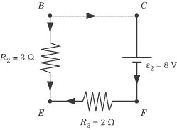
Tracing the loop clockwise from B,
the arrows cross
e2,
but in the wrong direction, from positive to negative, meaning that the voltage
drops by 8 V. Next, the current crosses
R3 ,
with an additional voltage drop of
(l1 - l2)R3 .
Finally, it crosses
R2,
but in the opposite direction of the arrows, so the current goes up by
l2R2.
Now we can construct a second equation:
-e2 - (l1 - l2)R3 + l2R2 = 0
-8-2 (l1 - l2) + 3l2 = 0
l1 = 1/2 l2 - 4
Plugging this solution for
l1
into the earlier equation of 4l1
+ 3l2 = 12, we get:

So the current across
R2
is 28/13
A. With that in mind, we can determine the current across
R1
and
R3
by plugging the value for
l2
into the equations we derived earlier:

The negative value for the current across
R3
means that the current actually flows in the opposite direction of the arrow we
drew. This makes perfect sense when we consider that current should normally
flow out of the positive terminal and into the negative terminal of battery
e2.
It doesn’t matter how you draw the current arrows on the diagram, because if you
apply Kirchhoff’s Rules correctly, you will come up with negative values for
current wherever your current arrows point in the opposite direction of the true
current. Once you have done all the math in accordance with Kirchhoff’s Rules,
you will quickly be able to determine the true direction of the current.
Next to display next topic in the chapter.
Practice Questions
Video Lessons and 10 Fully Explained Grand Tests
Large number of solved practice MCQ with explanations. Video Lessons and 10 Fully explained Grand/Full Tests.